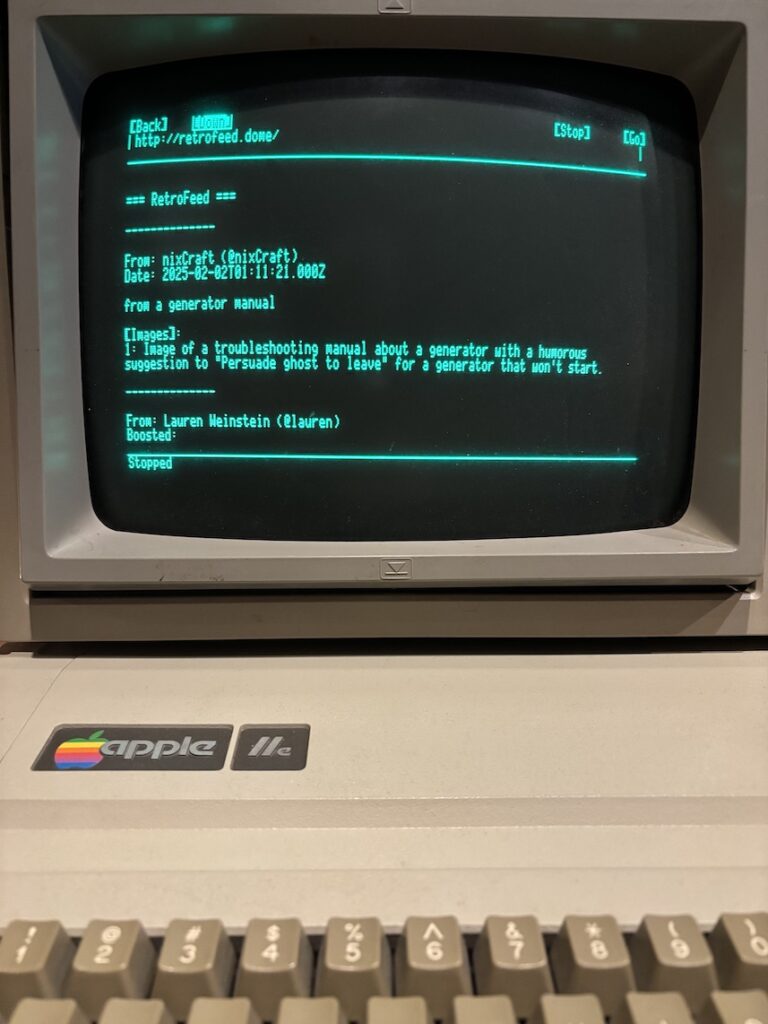
Wanting to deepen my understanding of Apache Tomcat and enterprise Java web architectures, I decided to create something practical that would force me to engage with various aspects of Tomcat deployment and configuration. Introducing RetroFeed, a proxy server that transforms Mastodon feeds into plain text for the terminal or text-only HTML for vintage computers.
The Project Concept
The idea: create a web application that would allow vintage computers running text-based browsers, or even curl on the command line, to read Mastodon feeds. This required not just implementing the Mastodon API integration, but also careful consideration of content delivery and compatibility with older HTTP clients.
Transforms rich Mastodon content into terminal-friendly text
Handles boosts (reblogs) with proper attribution
Displays image alt-text descriptions
Smart content negotiation: serves HTML to browsers, plain text to curl
Self-hosted on your local network
Configurable for any Mastodon instance
Technical Architecture
The application is built on a multi-tier architecture:
Presentation Layer
Transforms modern social media content into HTML 2.0 compatible format
Uses basic HTML elements for maximum compatibility
Handles character encoding and content formatting
Content negotiation based on User-Agent
Application Layer (Tomcat)
Servlet-based implementation
Configuration management for API tokens
Content transformation pipeline
HTML/plain text rendering logic
Integration Layer
Mastodon API client
Content fetching and parsing
Error handling
Why Tomcat?
While this could have been implemented using lighter-weight frameworks, using Tomcat provided several learning opportunities:
Servlet lifecycle management
WAR file deployment
Container configuration
Security settings
Multi-tier architecture design
Proxy configuration
Key Learning Points
1. Servlet Configuration
I learned how to properly structure a web application’s deployment descriptor (web.xml) and how to use annotations for servlet mapping.
2. Configuration Management
One interesting challenge was securing the Mastodon API token. This led to implementing a configuration service that loads settings from an external file, keeping sensitive data outside the WAR file.
3. Content Type Handling
Perhaps the most interesting technical challenge was ensuring compatibility with both modern and vintage clients. This required careful attention to User-Agent detection and content type handling:
Challenge: Modern web standards don’t work with vintage browsers
Solution: Implemented strict HTML 2.0 compliance and proper content type handling
Security
Challenge: Protecting API tokens in a web application
Solution: External configuration file with proper filesystem permissions
Content Transformation
Challenge: Converting modern social media content to text-only format
Solution: Custom transformation pipeline with HTML sanitization
Media Handling
Challenge: Making image content accessible in text-only format
Solution: Implemented alt-text display for images
Looking Forward
This project served as an excellent learning vehicle for understanding Tomcat’s architecture and configuration. It forced me to think about:
Proper separation of concerns
Security considerations
Configuration management
Content type handling
Proxy configuration
Backward compatibility
While a simpler framework might have been more appropriate for this specific use case, building it with Tomcat provided valuable experience with enterprise Java patterns and deployment scenarios.
Try It Yourself
The project is open source and available on GitHub. If you’re interested in learning about Tomcat or just want to read Mastodon on a vintage computer, feel free to check it out and contribute!
What started as a learning exercise turned into a functional project that not only helped me understand Tomcat better but also created something useful.
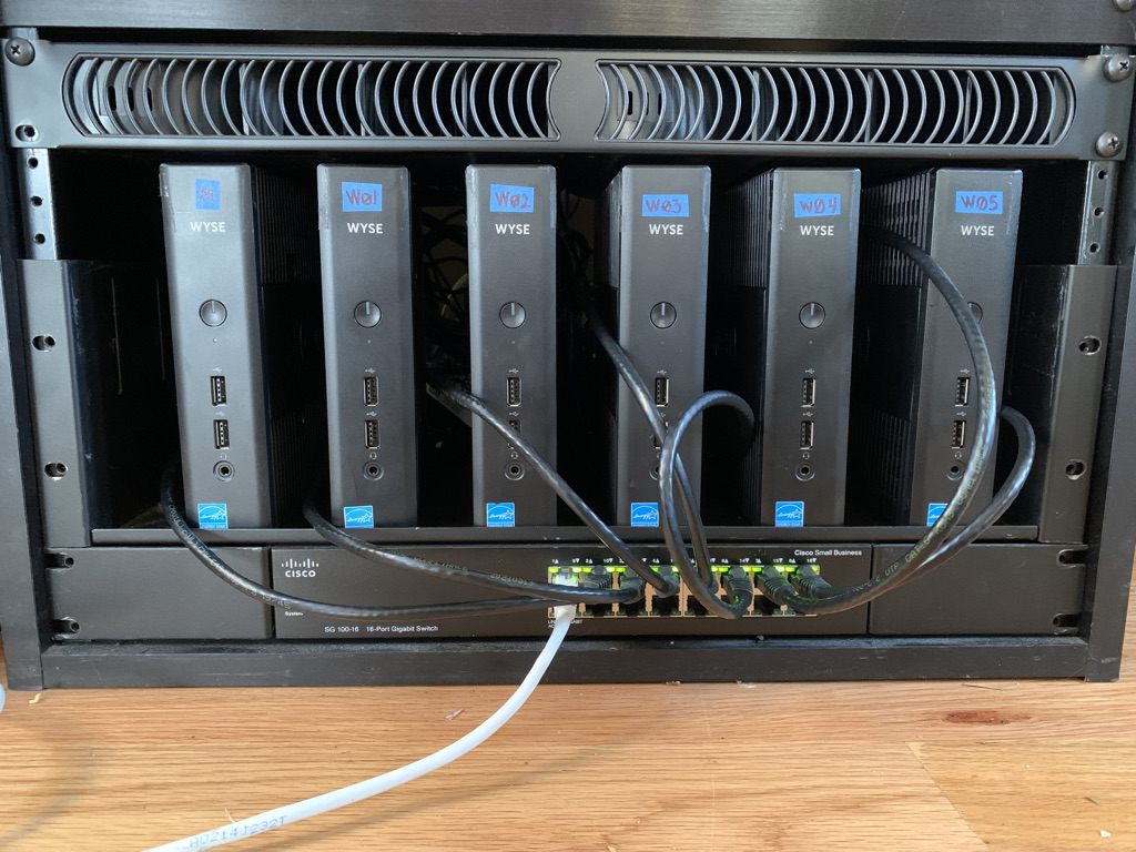
I’ve been wanting to learn Kubernetes for a while and I suppose I could have just installed minikube on my laptop, but where is the thrill in that? I want an actual cluster with multiple bare metal nodes. I was inspired by some of the Raspberry Pi projects I saw online, but I’m too cheap to go out and buy 6 Raspberry Pis. Instead, I scored 6 Dell Wyse 5060 Thin Clients on eBay for a little over $30 each. These babies sport an AMD steppe Eagle GX-424 2.4 GHz Quad Core processor, so that’s 24 cores to work with. Awww yeah. cpubenchmark.net gives these an average CPU mark of 1761, as compared to the Raspberry Pi’s 734. My units also came with 4GB RAM and a 16GB SSD. The power consumption is 7.8 watts at idle, which is a bit high compared to the Raspberry Pi’s minuscule 2.875 watts, but still not bad. For reference, an iMac 27″ consumes about 40 watts at idle.
K3S is the obvious choice for lightweight hardware like this. There are a number of ways to set it up, and I could have certainly just installed Linux on each one from a USB stick and then logged in and installed K3S, but we are living in the era of infrastructure as code, so this deployment had to be automated!
I decided to run Flatcar Linux, which is a fork of Red Hat’s CoreOS. Flatcar is a lightweight “container Linux” which is “designed from the ground up for running container workloads. It fully embraces the container paradigm, including only what is required to run containers.”1
Along with the 6 nodes, I would need a provisioning server to support PXE booting the nodes and applying a separate image to each one. My goal was a zero touch deployment, but I did end up having to do a little bit of touching here and there. For one thing, I had to change the boot order in each client’s BIOS settings to put PXE boot ahead of the SSD. This was easier than erasing ThinOS from the drives.
Broadly, the deployment of a node follows this process:
The node boots in PXE mode and makes a DHCPREQUEST.
The DHCP Server assigns a static IP address based on the node’s MAC address.
PXE boot continues with a custom PXE file based on IP address.
The PXE boot file specifies an HTTP hosted ignition file, customized for that node. (Ignition is similar to cloudinit, with some advantages for this type of deployment).
The first ignition file checks to see if this is the first boot, and if it is, handles the OS installation to disk and specifies a second ignition file for subsequent boots.
We turn off the PXE server and manually reboot the node and upon second boot, the first ignition file is ignored (because it’s not the first boot anymore) and the second ignition file runs.
The second ignition file checks to make sure K3S is not already installed, and if it’s not, installs K3s and joins the node to the cluster.
Network Environment
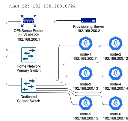
The cluster is connected to a separate switch and lives on its own VLAN with the subnet 192.168.200.0/24. My gateway router is an OPNSense box, so I created the VLAN there, trunked it to the switchport that’s connected to the cluster switch, and disabled DHCP for the segment in the router settings, since I would be running DHCP service on the provisioning server.
Provisioning Server
I installed and Ubuntu Server 22.04.1 on the provisioning server and applied updates as well as the necessary packages:
I was not about to squint at a tiny label and manually type the MAC addresses, so I connected and powered on each one and ran
systemctl status isc-dhcp-server
The MAC addresses can be copied and pasted from the results:
Feb 09 01:52:54 pixie dhcpd[2799]: DHCPREQUEST for 192.168.200.11 from 84:7b:eb:ef:7d:41 via enp2s0
Feb 09 01:52:54 pixie dhcpd[2799]: DHCPACK on 192.168.200.11 to 84:7b:eb:ef:7d:41 via enp2s0
Next, I configured the tftp server by editing /etc/default/tftpd-hpa
Next, I created a PXE boot file for each node. In order to be associated with that node, the filename should be the node’s IP address in hexidecimal form. For exmaple, here is my node-1 PXE boot file which will be applied to the client with IP 192.168.200.11. BTW, the hexidecimal filename must be in ALL CAPS. I killed a little time figuring that out:
Notice how the PXE boot file hands off the boot process to the node-1 ignition file on the last line. So now we need to start apache2 and serve up the ignition files for the next stage of deployment. I highly recommend reading about ignition here: https://flatcar.org/docs/latest/provisioning/ignition/
We want our installation ignition file to run on the first boot, and then the “ignite-boot” file for any subsequent boots. To identify the first boot, Ignition relies on GRUB to check for the presence of a file at flatcar/first_boot but PXE clients don’t use GRUB, so we have to appended first_boot as a boot argument in the PXE file. The first ignition file handles OS installation, then after a reboot, the OS will look to a second ignition file for configuration and services (K3s, in our case). The ignition files are written in yaml, and then transpiled into JSON format (more on that later). Here is my node-1 ignition file in yaml form. An ssh public key is added here for remote login:
Note the handoff at the end to the next ignition file, node-1-ignite-boot.ign. That file sets the hostname and deploys K3s. Again, this is the human-readable yaml form which will be transpiled to JSON before serving:
Note the Environment variable which is set for node-1 as "INSTALL_K3S_EXEC=--cluster-init"
For subsequent nodes, the Environment variable will be set to "INSTALL_K3S_EXEC='--server' 'https://192.168.200.11:6443'"
Next, the ignition files are transpiled to JSON format and placed in the /var/www/html directory. The tool to use is container-linux-config-transpiler which seems to do some special formatting, so this tool should definitely be used rather than another yaml to JSON converter.
Booting the Nodes
Once the provisioning server was configured with 6 custom PXE boot files, 6 node-x-ignite.ign files, and 6 node-x-ignite-boot.ign files, it was time to boot the nodes! I booted each one in succession and once they were all responding to pings, I shut down the tftp service to prevent PXE booting on any subsequent reboots. Then I ssh’d into each node (note that the hostname is “localhost” becasue we haven’t run our second ignition file yet) and rebooted. Upon the second boot, nodes get their hostname and K3S downloads and installs! I logged into node-1 which now greets me with its proper hostname and checked the list of nodes:
core@node-1 ~ $ sudo k3s kubectl get nodes
NAME     STATUS     ROLES
node-1   Ready      control-plane,etcd,master
node-2   Ready      control-plane,etcd,master
node-3   Ready      control-plane,etcd,master
node-4   Ready      control-plane,etcd,master
node-5   Ready      control-plane,etcd,master
node-6   Ready      control-plane,etcd,master
Six nodes, ready to rock!
Conclusion
Overall, I’m pleased with the outcome of this project. I was able to automatically provision a bare metal kubernetes cluster on cheap, low-power hardware which will be easy to maintain and upgrade over time. If I want to add another node, I can simply give it a static IP address and clone a few files before attaching it to the network and booting up. I look forwarding to digging in deeper into kubernetes topics and deploying some workloads to the cluster.
In this video, I explain subnet masks for the beginner, or anyone who never quite understood subnet masking. I created this video as an exercise in instructional video making. I hope you find it useful.
In computer science, parity data is like a magic trick. When students first learn about RAID, the concept is often glossed over, and only the attributes of parity data are explained: data from one drive can be used to recover from a loss of any other drive in the array, even though the size of the parity data is equivalent to only one drive’s capacity. In other words, if you have 10 hard drives in an array, you can use 9 of them for data storage and the remaining single drive to provide a backup for all the others. How is this possible?
The power of parity data lies in the binary nature of computer data. Let’s imagine a simplified version of a RAID array of four drives, utilizing striping with parity. The first three drives will be used for data, and the fourth drive will be used for parity. To keep things simple, let’s imagine that the stripe size is only one bit so the first stripe might look like this:
The RAID controller writes the ones and zeroes to each drive, and when it comes to the fourth drive, it calculates the parity data. It writes either a one or a zero: whichever would make the total number of ones even. In this case, since there is only a single one, the controller writes another one, to make it even.
Now, if any of the first three drives fail, the contents can be inferred from the parity data. For example, let’s say the first drive fails:
The RAID controller knows that the number of ones needs to be even, but there is only a single one left in the stripe. So it infers that drive one contained a one. If drive two or three fails, no ones would need to be added to make the number of ones even, so the controller would know the drive contained a zero. As long as only one drive fails at a time, its contents can be inferred by looking at the parity data and the data on the other drives.
And that’s how parity data works! Of course, in a real RAID array, the stripe size would be much larger and the parity data would be distributed across the drives. But the concept is the same. The storage capacity of a RAID 5 array is (n-1)x where n = the total number of drives and x = each drive’s capacity. Only a single drive’s worth of capacity is needed for parity data, and RAID 5 offers a nice balance of the benefits of performance and redundancy.
Note that RAID 5 is falling out of use in modern production environments in favor of RAID 10. Hard drives have gotten larger and cheaper, making it more cost effective to use mirroring rather than parity. RAID 10 offers the performance benefits of striping and the redundancy of mirroring, and allows 50% of an array’s capacity to be used.
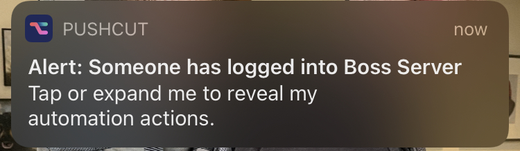
I recently spun up a RHEL 8 server on my favorite cloud service to use as part of my study lab for RHCSA. I created a login for my brother, who is also studying similar topics. I thought it might be fun to ambush him with some silly messages using the write and wall commands the next time he logged in, but how would I know when he does? I needed to generate a notification when he logged into the server. I had recently discovered pushcut: an amazing app that allows you to generate custom push notifications to your iPhone. Check it out at https://www.pushcut.io/ and download the app. Pushcut is free for basic functionality, including the creation of custom push notifications triggered by a webhook. So to generate the push notification, all I needed to do was trigger the following command whenever someone logged in to the server using SSH:
curl -X POST https://api.pushcut.io/<webhook-string>/notifications/Boss%20Login%20Alert
After a little research, I determined that the best approach would be to write up a shell script and trigger that from the PAM (Pluggable Authentication Module) event.
#!/bin/bash
if [ "$PAM_TYPE" != "close_session" ]; then
curl -X POST https://api.pushcut.io/<webhook-string>/notifications/Boss%20Login%20Alert
fi
The script is saved to /usr/local/bin/login-notify.sh. Then, to set it to be triggered by a PAM login event, just append this line to the end of /etc/pam.d/sshd:
That’s it! He’ll never see it coming! This solution is not a replacement for a proper IDS in a production environment, but there are many scenarios where you’d like to know when someone logs into a Linux box. MacOS also uses PAM, so it should be possible to adapt this technique for Mac as well. If you have found a creative use for it, please leave a comment below.